Today I was thinking that schematic was begining to get tough !
So I thougt that the external boards could provide me capital information on what signals where on the various connectors, and that if I could get the connectors' signals functions from the external board, It would ease the understanding of the main board !
So today I was investigating on a insertion motor from one of the PS3 I have to repair, an so I started with the associated board.
Here are the parts :

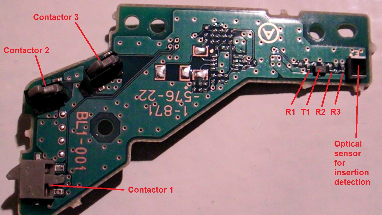
So the board is the BL1-001.
The motor is the FF-050SB-11170 and its datasheet is available on the internet.
I remind you that this motor is assuming the insertion, ejection, disk manipulation to drop it on the spindle motor.
It can be tested just by applying a 7V voltage between its pins in both ways, motor axis should rotate fast in both cases.
Here is the board analysis for the top side :

And for the bottom side :
What we can see is that many components are not mounted.
The board functions are :
- Motor connection
- Contactors
- Insertion sensor
And now here is a fast schematics :

I've measured that 9 pin is GND.
I've also measured that 8 pin is Power supply and it is directly taken on pin 1 from the 60 pins PS3 connector.
I finally decided to draw the schematics with Word as they are easily and quickly done and they can be used by anyone. The schematics tools I wanted to used is way too heavy to handle for the time I can spend on it, and finding the components symbols I need is a real pain in the ass as I would have to create most of them !
So the word solution seems fine !
Well, that's all folks for today.

No comments:
Post a Comment