Bonjour,
Si vous trouvez mon blog utile, merci de m'aider à continuer à l'enrichir en faisant un don via PAYPAL (Bouton en haut à droite).
Cela me permettra d'acheter du matériel pour faire des tests et de réaliser des cartes électroniques de test.
Merci !
Hi,
If you find my blog useful, thank you helping me to keep adding useful information by making a donation with PAYPAL (top right corner button).
This will let me buy hardware for tests and design electronic boards for test purpose.
Thanks !
Tuesday, December 28, 2010
Monday, December 20, 2010
Service de diagnostique / réparation
Bonjour à tous !
Après de nombreuses heures de travail pour comprendre le fonctionnement de la carte fille du lecteur Blue Ray, j'ai réussi à faire des synoptiques et des bouts de schéma. Mais surtout je me suis fais un "check list" de points à vérifier pour diagnostiquer les pannes sur cette carte.
Depuis que je me suis penché sur le sujet, j'ai mis à disposition, à travers mon blog et mes posts sur les forums beaucoup d'informations sur mon travail. Cette fois, je souhaite faire fructifier ce travail en proposant un service rémunéré de diagnostique / réparation des cartes filles BMD-001 et BMD-002, ce que je pense vous comprendrez vu la quantité de travail que cela représente !
Je peux également faire ce travail de diagnostique/réparation au niveau du lecteur blue ray complet.
Mon offre est la suivante :
- Vous remplissez le formulaire de demande ci dessous pour démarrer la prestation et confirmer votre accord sur le contenu.
- Vous m'envoyez votre carte fille / lecteur dans un emballage adapté.
- Vous y joignez votre participation financière pour le temps passé.
- Vous me fournissez une liste détaillée des symptômes constatés, des manipulations effectuées, des réparations réalisées, etc...., ceci afin d'orienter les recherches.
- Je vous tiens au courant au fur et à mesure des avancées du diagnostique,
- Je vous informe de toute panne identifiée, de ce que cela implique comme réparation et si je suis en mesure de la réaliser.
- Vous choisissez de me confier la réparation ou non.
- Je fais les modifications et les tests.
- Je vous fournit un rapport détaillé de tout ce qui a été fait.
- Je vous renvoi votre carte fille / lecteur dans son emballage adapté.
Je demande une participation de 50€ qui inclue :
- Diagnostique / réparation
- Document de compte rendu
- Frais de port de retour
- Composants de rechange
Formulaire de demande à adresser à stefde69@gmail.com :
- Référence de la carte fille (BMD-001 / BMD-002) :
- Le disque est avalé ? (Oui/non) :
- Le disque est éjecté ? (Oui/non) :
- Le faisceau laser est présent ? (Oui/Non) :
- Le disque tourne de manière constante? (Oui/Non) :
- Manipulations effectuées :
- Modification éventuelles réalisées :
- Autre :
Si vous êtes Ok sur le mode opératoire présenté, je vous donnerais par mail mes coordonnées pour envoi de la carte/lecteur.
N'hésitez pas à me contacter sur stefde69@gmail.com si vous avez des questions.
Réparations effectuées :
- 16 blocs optiques changés
- 2 bloc optique sauvé par nettoyage lentille, plein de poussière et gros fumeur !
- 1 problèmes mécaniques insertion/ éjection résolu.
- 5 connecteurs de nappe blue ray changés
- 1 erreur 8002F14E résolue
- 1 erreur 8002F147 résolue
- 1 Ethernet HS corrigé
- 1 capteur d'insertion réparé.
- 2 Cartes fille alimentation HS réparées
- 1 Remplacement CXA2720R.
- 2 Reprise remplacement BD5976FS + composants autour
For now I do not provide this service outside France as shipping costs would be too expansive.
Sunday, October 24, 2010
Solving thermal problems on your PS3 !!
Hi,
Everyone has read on the internet people complaining of thermal shutdown security activation, YLOD as a consequence of repeated overheat problems.
In fact it seems that SONY has prefered silence to efficiency on its implemention of the PS3's fan regulation !
You might have tried the fan test on start up ? Well it will give you a noise reference when the fan is at a full 100% command, which is quite impressive and close to an helicopter !
So I thought, well let's see what SONY has really done in the fan regulation with some measurements on the PWM command Fan of a 60Go PS3, which is well none for having the biggest thermal problems of all models.
Ok, then I have the fan activation law on that model, then I said to me, well, if we're not happy with SONY's configuration why not doing our own manual fan command ?
Well, this is what this article is all about, and I will explain to you what measurements I've done, what design I've made and what are my conclusions !
Part 1 : 60Go PS3's fan regulation law : the PS3 probing
First of all what do we need ? :
- The fan command is done using a PWM signal whoseratio is modified to adjust the rotation speed. If PWM is 10%, fan rotation is slow and very quiet, if PWM is 90%, fan rotation is fast and very noisy. So we've got to measure the PWM signal, I used my oscilloscope.
- The goal of the fan is to evacuate a heat quantity depending on its speed rotation. The effect is on the internal temperature of the PS3, so I measured the internal temperature with a thermocouple associated with a multimeter. My goal was to have a image of the overall internal temperature, not the temperature of one or the other CPU.
- The third parameter that would have been interesting is the noise measurement (Decibel meter) that would have told us the highest PWM to reach to still ear the game playing ! But infortunatly I didn't found one.
So here we are, internal PWM and temperature measurements, in the real conditions, it means : PS3 closed and the measurement wires coming out of the PS3 to access them.
This picture shows where I placed the thermal sensor, right in the heart of it ! Between power supply and blue ray drive for the upper parts, and between the CPU and GPU for the lower parts. Then the wire goes out of the PS3 througt the hard drive location.

The PWM signal is probed on the Fan connector.
On the following picture we can see the measurements wires getting out of the PS3 :

And in the next picture here is all the experimentation :

On the left the 60Go "under test" PS3.
In the middle the multimeter with the thermocouple wire from the inside of the PS3.
On the right the oscilloscope with the PWM wire from the inside of the PS3.
Part 2 : 60Go PS3's fan regulation law : the measurements
The way it is done :
- As thermal process is slow, I defined a time base of 5 minutes between each measurement.
- I measured the temperature when the PS3 was off, to have the ambiant environmental temperature, which I remind you is a main parameter. The higher the ambiant temperature is, the quicker the temperature evolves and the higher it gets, increasing all risks !
- Then I powered on the PS3 and let it wait in the XMB to warm it up.
- Next, I insered the James bond Casino Royale Blue ray which is automatically launched and starts with some previews and other stuffs to get waiting in the film's menu. This will make the PS3 run in full HD mode which will be a medium stress for the PS3, but will let me do my tests on a long time as the PS3 will use the same calculation power all along the movie, so generating the same heat approximatively.
- First, I will use analog video output and then I switch to HDMI to see if it has some inpact on the parameters measured.
- Finally, I will use my only game "resistance" to get the PS3 more stressed and to see how measured parameters evoluate.
So here are the results :

The first conclusion is that the PS3's regulation doesn't change that much as it stayed at 27.5% during all the time I made the measurements, but the temperature changed only on a 3°C delta.
If we draw the parameters we get :

Part 3 : Manual regulation law : the explainations
I realized that I don't have a game that can really load the PS3 to get it really heat and reach higher temperatures.
But it is not that important as I can deal it in another way !
I know that the PS3 regulation keeps the température to 40-43°C with a 27.5% PWM.
Now that I can manually fix my PWM ratio, what will be the temperatures in the PS3 in the same conditions ?
I'll come to it, but let see how I made my measurement this time.

In the previous picture you can see that I've made a custom PWM generator with a PWM command by a potentiometer !
On the left a old DVD power supply that delivers the 12V power supply.
In the middle my little design.
On the right a PS3 fan system connected to my custom system.
That's how I made it work, so now I can drive the PS3's internal fan !
But first problem, extand the fan's wiring to reach the external command !

And now the overall measurement system !

Now I can make MY temperature control and measurements !
Part 4 : Manual regulation law : the measurements
To compare similar things I have to make the same measurement conditions.
- I made a ambiant temperature measurement PS3 off,
- I made the PWM modifications and measurement on the Blue ray movie James Bond Casino royale playing
- I have to start the PS3 with a close ratio to 27.5%, I will use 23.9% as my potentiometer is not that accurate !
- I increased the PWM ratio to make the temperature decrease.
Problem reached !!!
The PS3 shut down in thermal protection as I reached 40°C with a 23.9% regulation, so regulation was to low which gives us a rule to respect, the manual system shouldn't allow too low PWM ratios. As they are controlled manually, if the user does not pay attention the PS3 will shut down with shutdown protections, so a minimum PWM should be provided by the manual command.
- So I started over with a higher starting PWM ratio of 36.8%.
- Then I increased the PWM to see temperature evolve
- And finally I decided to go back in low PWM to see if system shuts down again, which didn't, so in order to not destroy the PS3 I stopped !
Here are the results :

And now, the most important of all, a drawing of the temperature law depending on the PWM command ratio !!

CONCLUSION
Now we can see that using a manual Fan command can really make us reduce the system temperature, but You'll have to know that the noise will increase too !
In my tests, temperatures variations are not that big, but in cases where temperatures get higher the result should be proportionals !
So YES, I have a design that can be added inside your PS3 to let you adjust the temperature and probably avoid the YLOD in time !
I will soon work on providing a small product dedicated to the PS3 to manually control the fan !
Tuesday, July 6, 2010
BD7956FS implementation
Hi !
Just found some time to start writting down the schematic section for the BD7956FS interface.
I started with the spindle motor connector and I will add little by little the other stuff I identify !

This should help you to diagnosis and repair the sled / spindle / insert motor problems !
See the previous article like on the spindle motor board analysis for understanding.
TP stands for test point.
C5 is the 5V_2 power supply decoupling capacitor.
R4 is a pull up resistor to force the inactive state for the switch SW1 information.
R1/C4 is a filter to debounce the switch SW information that is send to the CPU.
All the other signal for the spindle are directly driven by the BD7956FS.
We can find the 3 PWM commands U,V and W, and the Hall sensing return signals for the motor controller.
Pins 35/40 : this goes to the BA5888FP, after looking at the datasheets this signal should be the Vcenter.
Pins 49/50/51 : after looking at the datasheet it looks like the power supplies for the sled section as noted SLVdd, SLRNF1 and SLRNF2.
These power supplies are filtered from the 12V_2 supply with the following RC filters R6/C10 and R5/C9.
Another power supply is generated from the 12V_2, it is filtered with the L1/C11 filter.
Added the Insert/Eject interface.
The motor control is simplier than the spindle as there are only 2 wires.
The optical flag is filtered with R7/C13 before going back on the PS3's main board using the 60 pins connector.
Several TP are placed on the various inputs of the Insert/eject board. They are grouped on the solder side into some kind of a test connector which must be used by SONY during the production tests to force test stimulis on these inputs.
Some of the NM (not mounted components on the Insert/Eject board) pins are attached to simple TP. But some and the SWx inputs are associated with a piece of design using several small components that I can't identify for now ! I'm having some reflexion on how I can have the schematic anyway. Maybe with some blackboxes ?
Any feedback is welcome !
Saturday, May 29, 2010
The difficult but interesting part !
Hi !
I've started the schematic of the BD2956FS and BA5888FP controllers, the various interface connectors, power supplies, in a word, all the control parts of the board !!
You can imagine it's quite complex so it will take some time !
Coming soon....
Numeric heart of the board will come after !
I've started the schematic of the BD2956FS and BA5888FP controllers, the various interface connectors, power supplies, in a word, all the control parts of the board !!
You can imagine it's quite complex so it will take some time !
Coming soon....
Numeric heart of the board will come after !
Saturday, May 15, 2010
Spindle motor
Ok, so I tried this motor this time!
But again no information on the Internet or on NIDEC website.
Only found that it is a small Brushless DC motor, and that there is a switch contactor on the board.
So this Brushless DC motor is build with a permanent magnet rotor and 9 poles wired around stator. 3 Hall sensor are labelled H1, H2 and H3 on the board, they are used to identify the rotor position. The motor command is 3 PWM signals that are used to create the magnetic field that will make the motor work.
On the following picture the wiring of the 3 poles is identified :

I didn't have a dead board so I couldn't destroy it to identify the whole schematics ! Here is what I got :

?? means that I couldn't make measurements on the board.
There are several traces that go under the spindle motor mostly to the Hall sensors, but I couldn't identify the schematics.
Well next step will be the associated connector on the main board which seems to lead quite easilly to the BD2956FS. And in fact the goal will be to have the interconnexion between the 2 motor controllers and the 4 associated connectors.
If I have some time it would be fun to open a dead optical module to get some clues on its connector's pinout and functions.
Sled Motor
No luck today !
I tried to find information on this motor but got nothing on the Internet !

Anyway, there is no electronics on this part so I'll figure out the connector's signals from the main board.
If you have datasheet or technical information about this motor please share, so I can update.
I tried to find information on this motor but got nothing on the Internet !

Anyway, there is no electronics on this part so I'll figure out the connector's signals from the main board.
If you have datasheet or technical information about this motor please share, so I can update.
Wednesday, May 12, 2010
Insertion - Ejection Motor board
Hi there,
Today I was thinking that schematic was begining to get tough !
So I thougt that the external boards could provide me capital information on what signals where on the various connectors, and that if I could get the connectors' signals functions from the external board, It would ease the understanding of the main board !
So today I was investigating on a insertion motor from one of the PS3 I have to repair, an so I started with the associated board.
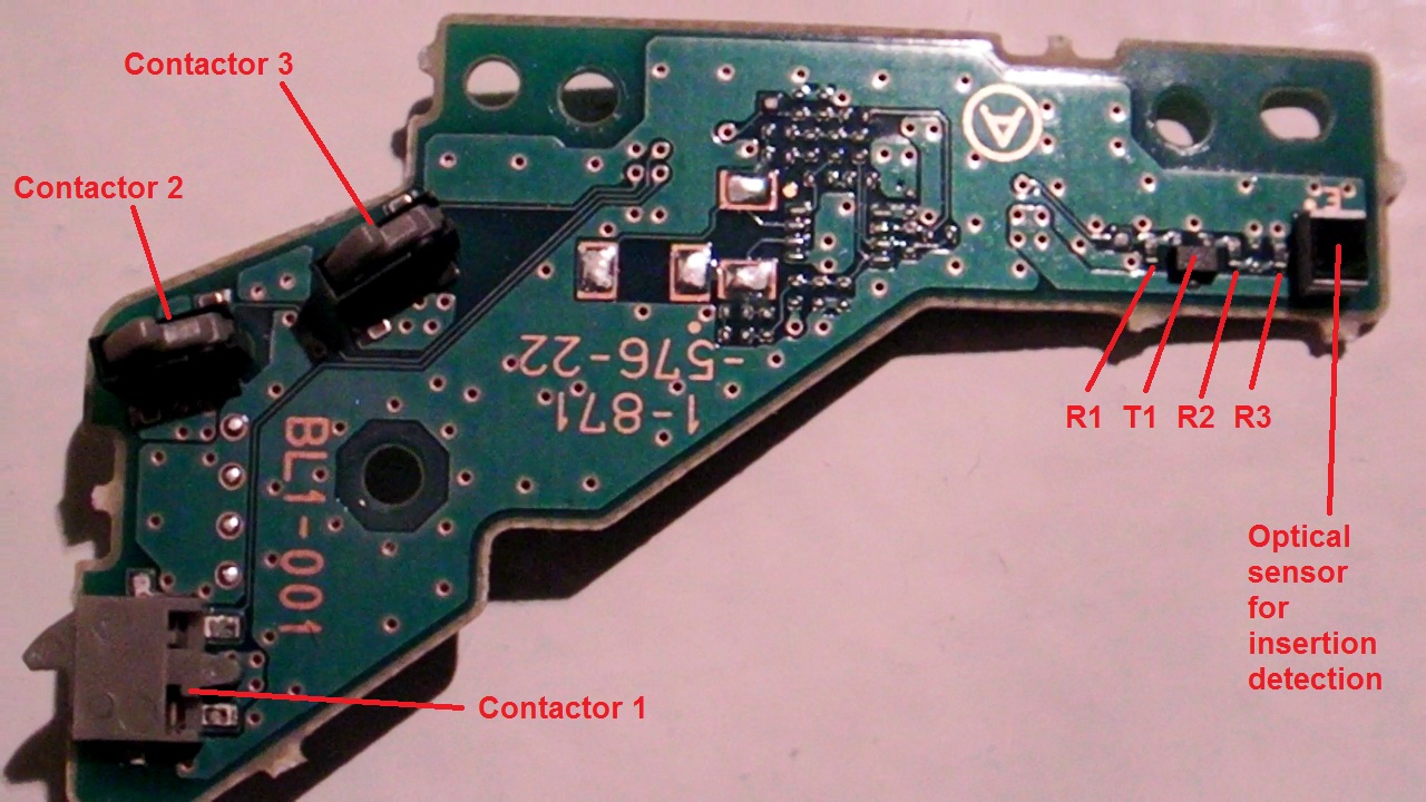
Here are the parts :

So the board is the BL1-001.
The motor is the FF-050SB-11170 and its datasheet is available on the internet.
I remind you that this motor is assuming the insertion, ejection, disk manipulation to drop it on the spindle motor.
It can be tested just by applying a 7V voltage between its pins in both ways, motor axis should rotate fast in both cases.
Here is the board analysis for the top side :

And for the bottom side :

What we can see is that many components are not mounted.
The board functions are :
- Motor connection
- Contactors
- Insertion sensor
And now here is a fast schematics :

I've measured that 9 pin is GND.
I've also measured that 8 pin is Power supply and it is directly taken on pin 1 from the 60 pins PS3 connector.
I finally decided to draw the schematics with Word as they are easily and quickly done and they can be used by anyone. The schematics tools I wanted to used is way too heavy to handle for the time I can spend on it, and finding the components symbols I need is a real pain in the ass as I would have to create most of them !
So the word solution seems fine !
Well, that's all folks for today.
Today I was thinking that schematic was begining to get tough !
So I thougt that the external boards could provide me capital information on what signals where on the various connectors, and that if I could get the connectors' signals functions from the external board, It would ease the understanding of the main board !
So today I was investigating on a insertion motor from one of the PS3 I have to repair, an so I started with the associated board.
Here are the parts :

So the board is the BL1-001.
The motor is the FF-050SB-11170 and its datasheet is available on the internet.
I remind you that this motor is assuming the insertion, ejection, disk manipulation to drop it on the spindle motor.
It can be tested just by applying a 7V voltage between its pins in both ways, motor axis should rotate fast in both cases.
Here is the board analysis for the top side :

And for the bottom side :
What we can see is that many components are not mounted.
The board functions are :
- Motor connection
- Contactors
- Insertion sensor
And now here is a fast schematics :

I've measured that 9 pin is GND.
I've also measured that 8 pin is Power supply and it is directly taken on pin 1 from the 60 pins PS3 connector.
I finally decided to draw the schematics with Word as they are easily and quickly done and they can be used by anyone. The schematics tools I wanted to used is way too heavy to handle for the time I can spend on it, and finding the components symbols I need is a real pain in the ass as I would have to create most of them !
So the word solution seems fine !
Well, that's all folks for today.
Monday, May 10, 2010
CPU pinout definition
For the CPU CXD5065GB-1 as I didn't find anything on a BGA 564 pins, I made an arbitrary pin identification for this component.
Here it is :

Here it is :

First look to the numerical sections !
Hi,
After the analog sections I've started to look to the numerical sections !
My first try is about the SPANSION Flash memory.
Here is some PCB analysis :

This is a closeup of the Flash's BGA package soldering.
The reference is AL008D0043-01, that's the marking on the package.
Of course this reference is under NDA so no datasheet is available for us !
Anyway, this component seems to be similar with the S29AL008D flash familly, where datasheet IS available.
What we can see first, is that an upper and a lower line of ball are spare because there are no trace leaving the balls. Must be to increase the component soldering, but anyway the E7 pin is connected to GND, so this can have a function.
Next, every pin on the datasheet can be found on the PCB as the pinout is always the same on these packages. And some of the not connected pins (NC) are used to increase the number of bits in the address bus to increase the memory's size.
Here I can identify 19 address lines plus 2 lines taken from the not connected ones.
Which would give us a 21 lines address bus.
Vcc and Vss pins have been confirmed on the board with my multimeter.
Another interesting thing to see is that every pin seems to be accessible using a via hole or by scratching the PCB traces to solder something on it to get a probe (using top and bottom, I can do some more measurements if you need it).
It is a pretty thougth thing to do, but for the ones who like to play, it seems possible to strobe the all memory's busses and have it going into a FPGA for example, and logging all bus accesses !
Ok that's done !
And feel free leaving a comment or answers to the open questions of the previous articles.
Sunday, May 2, 2010
Hi there !
I've found some time to examine (on the top side) another regulator section.
It is pretty close to the regulator 1 section as it is based on the TPS64203 Step down controller, a close friend of the TPS64201 !!
Here is a close up of the regulator components :

Here is the components identification for schematic :

I currently have a draft of this schematic, but the command circuit of the TPS64203's Enable input is getting deep into the board so it's harder to identify the schematic on this !
Here is the schematic of that section. I've made it with Word to have it quickly !
The Enable input is not complete, but it is linked with the rest of the board's design.

That's it for today !
Monday, April 12, 2010
Saturday, April 10, 2010
Power supplies study
Hi,
I will first start with the bottom side of the board which is mostly dedicated to power supplies generation and distribution.
On the following picture I've outlined various sections :
I will first start with the bottom side of the board which is mostly dedicated to power supplies generation and distribution.
On the following picture I've outlined various sections :

First we have the power supplies dispatchment which is mainly creating several supplies plans from the initial supply, starting with a ferrite bead which can serve as a fuse, some filtering with a inductor and a big output capacitor.
Secondly, there are secondaries voltages generated with regulators which are located in regulator sections 1 and 2.
And finally, a BA5888FP motor controller chip.
I will provide, as I finished them, analysis and schematics for these 3 sections.
A) Power supplies dispatchment
Here is a close up of the power supplies plans and components :

B) Regulator section 1
Here is a close up of the regulator components :

Next is a design taken from the TPS64201 Step down controller's datasheet, which is implemented by SONY on the board :
 C) BA5888FP section
Here is a close up of the Motor driver IC :
This is based on the following datasheet diagram of an equivalent component :
Ok, schematic tool in place !
Schematics available as soon as I edit them !
Coming soon .....
Blue Ray board made accessible
Hi,
On this picture you have the bottom face of the PS3 Blue Ray Drive's board controller :
Here the BMD-001 Rev1 board :

Most of the components can be accessed on their pins to put an oscilloscope probe, except the main processor SONY CXD5065GB-1 (BMD-002 board) or CXD5063AGG-1 (BMD-001 board), and the flash memory SPANSION AL008D0043-01 (BMD-002 board) or S99-50111-001 (BMD-001 board), because they are BGA.
So I had these components taken out to have access to their signals on the PCB :
Here the BMD-002 Rev 3 board :

So now I can do some reverse engineering on the schematics !
Wednesday, April 7, 2010
Board components
Hi,
I found a list from internet (can't manage to print it here !), it seems to be for a 60 Go version.
It is a very good start to have a component view of the board.
Only few components are not identified and I can't find any datasheets because they are SONY's components.
Hum, there seem to be several boards and several revisions for each board !!
I identified a BMD-001 and a BMD-002 board, are there others boards ?
For BMD-001 we have :
- ASIC / CPU / Video Decryption Device
Rev 1 : CXD5063AGG-1 Rev 2 : TBD Rev 3 : CXD5063AGG-1 Rev 4 : TBD
- ASIC
Rev 1 : CXD5064R Rev 2 : TBD Rev 3 : CXD5064R Rev 4 : TBD
- Interface controller
Rev 1 : CXA2720R Rev 2 : TBD Rev 3 : CXA2720R Rev 4 : TBD
For BMD-002 we have :
- ASIC / CPU - Video Decryption Device
Rev 1 : TBD Rev 2 : TBD Rev 3 : CXD5065GB-1 Rev 4 : CXD5065GB-1
- ASIC
Rev 1 : TBD Rev 2 : TBD Rev 3 : Suppressed Rev 4 : Suppressed
- Interface controller
Rev 1 : TBD Rev 2 : TBD Rev 3 : CXA2720R Rev 4 : CXA2720R
If anyone has technical information on these it would be great to share !
If you can help me filling the missing references that would be great.
As I'm filling this list in time, it seems that there are two board generations with the same main components. On the BMD-002 version, the CXD5064R ASIC and the CXD5063AGG-1 CPU were merged into the CXD5065GB-1 CPU.
I found a list from internet (can't manage to print it here !), it seems to be for a 60 Go version.
It is a very good start to have a component view of the board.
Only few components are not identified and I can't find any datasheets because they are SONY's components.
Hum, there seem to be several boards and several revisions for each board !!
I identified a BMD-001 and a BMD-002 board, are there others boards ?
For BMD-001 we have :
- ASIC / CPU / Video Decryption Device
- ASIC
- Interface controller
For BMD-002 we have :
- ASIC / CPU - Video Decryption Device
- ASIC
- Interface controller
If anyone has technical information on these it would be great to share !
If you can help me filling the missing references that would be great.
As I'm filling this list in time, it seems that there are two board generations with the same main components. On the BMD-002 version, the CXD5064R ASIC and the CXD5063AGG-1 CPU were merged into the CXD5065GB-1 CPU.
PS3, Blue Ray Board Analysis
Hi,
I'm French but I will try to do this in English so everyone can understand !
My goal is to get a good knowledge of the PS3's Blue Ray Controller board in order to ease repair or more !
So here is the amount of work there is to do :
- Reverse ingeneering on the schematics
- Understand board synopsis
- Understand security principles
- Components identification
- Provide blue ray drive work explanations
- And more....
This list will change in time, depending on what I find, information I get and support you will provide me !
So any technical data are welcome.
Cheers !
Subscribe to:
Posts (Atom)
