Bonjour à tous !
Comme vous avez pu le constater il ne se passe plus grand chose sur mon blog.
En effet je n'ai plus vraiment le temps ni la motivation.....
Je ne rajouterais donc rien, sauf si peut être un jour je retouve une idée motivante !
Cdlt.
Hi all,
As you can see there is no more activity here !
In fact I don't really have time for it nor motivation....
So there will not be updates, excepted if some day I find a motivating idea !
Cheer !
Sunday, November 25, 2012
Tuesday, October 4, 2011
ATX to PS3 power supply cable
Hi !
If you are interested I can build one or several cables for you.
- Price is 20€ per cable.
- There is no stock, cable is done on demand with about one week delay.
- Shipment costs are included for France and close countries.
Here is the user guide :
https://rapidshare.com/files/331181711/cable_datasheet.pdf
----------------------------------------------------------------------------
Bonjour!
Si vous êtes intéressé je peux vous réaliser un ou plusieurs câbles.
- Le prix est de 20€ le câble.
- Le câble n'est pas en stock il est réalisé sur commande avec un délai de l'ordre d'une semaine.
- Les frais de port sont inclus pour la France et les pays voisins.
Voici le mode d'emploi ici :
https://rapidshare.com/files/2862642519/manuel_utilisateur_cable.pdf
Friday, August 26, 2011
ATX to PS3 power supply cable
Hi,
I've just had a PS3 power supply that died !
So I said to myself, well why couldn't I replace it with an ATX power supply I've got. After all, it just provides +5V and +12V to the motherboard, and an ATX power supply does the job too.
Here are the details :
- PS3 startup command and ATX start up command are inverted, so to keep system simple, the PS3 will not start up the ATX using the command signal on the 24 pins connector. ATX start command will be forced permanently to ON and it will be switched on and off with its power switch.
- As I only have to provide +5V, +12V and GND to the motherboard, a standard male MOLEX 4 pins connector will be perfect to connect to any ATX power supply cable !
Still, there will be safety issues to take care off, such as wires compatibility with high currents, otherwise there are fire risks.
- As the PS3 power supply is useless, I take it off, and in the same way, I take the PS3 back switch block off too, in order to pass the ATX to PS3 adaptator cable inside the PS3. In this way we can still use the case of the PS3 and keep the cooling system efficiency.
Ok and here we are, I built an "ATX to PS3 adaptator cable" prototype !
Unfortunately my ATX power supply only provides 6A on +12V, so the PS3 starts up, Led goes green, but as I ear the Hard drive work and the screen blink, the PS3 shuts down with 3 beeps, and orange led blinking.
I have to find a power supply with much more power to finalize this !
Ok, I found a 300W ATX power supply with 13A on the +12V and it worked fine.
PS3 started and went to the XMB.
My PS3 has no wifi board and no Blue ray drive, in order to decrease power needed.
Now I add the blue ray drive.
=> Still booting to XMB
Now I add the Wifi board.
=> Still booting to XMB
Well The PS3 is complete and it boots up, but it does nothing, it waits in XMB.
The only thing is that I can ear the ATX power supply's fan speed going higher pretty soon, even if the PS3 does nothing, just waiting in XMB. I guess we are a little limited with only 13A on the 12V. I'll have to stress the PS3 with a game for example, in ordre to see if 300W ATX is enougth.
I've done a little video of this stuff just to show you it works !
I intend to provide this adaptation cable for people interested.
I'll make a more stronger cable with the right connector and wiring.
This solution has the following advantages :
- This allows PS3 Power supply replacement when failing,
- This allows PS3 Power supply unit / motherboard diagnosis
- Having the power supply out of the PS3 reduces the internal heat production, temperature rising and reduces the YLOD risks.
Ok, I've defined the architecture for the cable and I've identified components references. The problem is that specifications are high, as for the current which is 30A on the +12V. Such connectors are sold 3€ each, so the global cable cost will be 15-20€ each !
HERE IT IS !!
This is the first cable prototype.

On top, the internal +5V stand by connector.
In the middle, the internal +12V power connecteur (40A capable)
On the bottom, the 3 external ATX MOLEX connectors.
It is design to provide up to 32A for the 60Go PS3 power supply.
All elements are choosed to meet these specifications.
The external ATX power supply should be able to provide up to 32A on its +12V outputs rails.
this first prototype is build with :
- 8 x 1mm² wires
- 1 5 pins connector
- 2 contacts for this connector
- 2 40A female plugs
- 3 4 pins ATX MOLEX connectors
- 8 MOLEX contacts
- 3 thermo pieces
- 1 braided sleeving
- Solder
- 1 hour of assembly work time.
I'm now ready to build several cables for the one of you interested.
The price is 20€ with shipment cost included.
More information at stefde69@gmail.com
But I'll do a dedicated article with explanations, specifications and user guide.
Coming soon !
Tuesday, July 26, 2011
Blue ray function lost after downgrade : some work
Hi,
Lot of people have lost the function of blue ray reading after downgrading, I'm one of them ! I've tried many many things found on the internet to get it back, without success. So I decided to work on this, with only one goal : repairing blue ray drives.
So I have 2 PS3 with this problem (a 60Go and a 40Go) and I don't know what were the last BR read as I don't know where the boards came from. So after applying the association procedure, everything is read by the drive, except blue ray films, which seems to be a DRL problem.
As I read on the internet this DRL stuff might be handled in the EEPROM of the board, which is a SPI memory. So I said to myself, the first thing to do would be to watch what are the actions on this memory in order to identify something on this problem !
OK, so I worked on a SPI spy tool for several weeks, and I got it working.
Here it is :

The first step of this project is to SPY the SPI bus of this memory.
Next could be read and write functions, in order to examin the memory content and modify it.
But for now I have the SPY thing, this is how it works :
- A FPGA does all the job
- A first vhdl part make SPI deserialization of the SI and SO lines of the SPI bus, using the CS_n and CLK lines.
- Every 8 serial bits a 16 bits word is written in a FIFO, with D[15:8] = SI and D[7:0] = SO, a 16 bit is used to flag the rising edge of the CS_n to end some instructions.
- On the other side of the FIFO a got a microblaze microntroller in the FPGA. His job is to :
+ Watch FIFO to see if data is available.
+ READ the data and store it in a SRAM memory. This is mandatory as printing analyzed data on the UART is to slow and FIFO gets full and data are lost.
+ Read back the SRAM memory when SPI traffic is done, and analyze data flow to provide memory protocol transactions on the UART to see what is beeing done on the memory.
- Thanks to the hyperterminal log are done and memory access can be analyzed.
So for now I've got the following logs :
- 60Go power up sequence
- 40Go power up sequence
This is quite a lot of data as the controller of the board seems to get configuration parameters of the drive.
- 40Go RED blue ray insertion sequence
- 40Go TRON blue ray insertion sequence
This is where the controler shall get DRL informations to see if it can allow playback of the movie.
As I don't know how to put them on this blog, I can provide theses files if you make an email request for it.
Ok, back from holidays, but can't work on it !
Here, it is about 39°C in my house, so I will not use my PS3 to keep them alive !
It is supposed to rain in a couple of days, so....
Coming soon....
Thursday, May 26, 2011
PS3 Thermal behavior identification
Hi,
Thanks to my tool I was thinking that I could do several things :
- A least ! I will be able to answer if the PS3 heats more when placed vertically or horizontally !
- Compare the temperature with and without case
- Compare the temperature between 40Go and 60Go
To do this, the first test step is to power up the PS3 and let it warm up for a defined time. The PS3 should always start from the same cold state which will be ambient temperature, so I will have to do each test when ambient temperature is always the same for the test to be relevant, otherwise I will have to do corrections on measurements.
A second step would be to do a test launching a blue ray for example.
If you have other test ideas, feel free to participate!
Results coming soon !
I'm modifying design to have it smaller, in order to fit in a CPLD and make my own electronic board ! So it takes some time and results will be delayed.
You surely have noticed but I don't have much time to work on this !
....
Friday, May 6, 2011
Thermal probe diagnosis tool
Hi,
I have made a direct application of my brand new thermal probe tool !
I had to repair a 60Go PS3 which was in YLOD.
I repaired it, and when I started it over, fan started to increase regurarly to reach full speed and to finally shut down the PS3 with the thermal warning message in the XMB.
So I probed the thermal probes of this PS3 and captured my tool's log in order to extract data. After some manipulations of the data I created 3 files for each probe of the PS3. Here are the graphics for each probe of the PS 3 :
Motherboard Probe graphic :

CELL Probe graphic :

RSX Probe graphic :

Measures are pretty relevant and thanks to them I clearly see that the CELL processor has its temperature rising and reaching the 85°C (which is the default thresholds of the thermal probes components) that generates the thermal alert interruption signal to the chipset, which leads the system to shut down with thermal alert message.
This confirms the fact that I used flux for the RSX during reflow and not for the CELL. I will have to run it again with flux on the cell this time, and I will check if there is some short circuit near the CELL.
So it is pretty fun to see that my tool works for diagnosis!
Tuesday, April 26, 2011
PS3 Thermal probes for fan control
Reproduction not allowed without permission.
Hi !
It is now time to present my new project : finding the thermal probes and analyzing their behavior toward fan control !
Confidential
As this is confidential materials, don't ask me the details I won't give them.
My goal is just to show what is possible, and I don't know yet the results !
Thermal Probe identifying on PS3 40Go
I spent a lot of time identifying components on the board, looking closely to get their marking and finding their datasheets !
And finally I GOT THEM, the thermal probes references and their datasheets !
They are three thermal probes components on the main-board.
- One for the RSX
- One for the CELL
- One for the main-board
The components for the RSX and the CELL have an external probe input, which must be connected to the CPU's and GPU's internal thermal probes. They also have both an internal thermal sensor. The third one is only internal sensor.
Reading the datasheets, is appears that there is a thermal alert control that must have been used by SONY to shut down the system. Maybe this is what is used when the XMB says that the system overheats and shuts it down.
Thermal system architecture
These all three components are SMB/I2C controlled, but they are slaves, so there must be a master in the system !
Starting from these components I used my multimeter to probe the main board and I finally found that they were related to the chipset of the main board. So it makes sense, as it is the same as in PC motherboards. The chipset configures thermal probes components, reads them with its firmware laws, and then with these information it controls the fan speed.
I guess it is all the same for the PS3 !
Let spy this !
I've started to probe a 40Go PS3 :

As I said, communication is a 3 wires I2C bus which has clock, bidirectionnal data and ground signals.
I've probed them on one of the thermal probes component, and now I have to design a I2C spy tool !

And as you can see on the front left of the test board there is a VGA connector which is directly accessed.
So now I have to design the test !
Complete system
Now I have the entire system :

Ok, first test design done, embedded logic analyzer is in place to watch I2C signals.
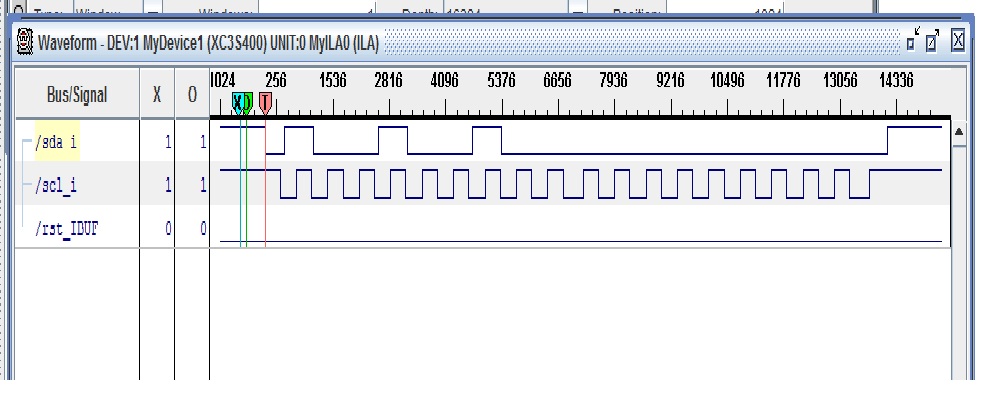
So I defined a trigger condition on a I2C START event to see I2C frames.
I armed the trigger and I powered up the PS3 at the back. Led is fixed red, PS3 in stand by, and there are I2C frames ! I Guess it is a security check to see if the PS3 can start in normal temperature conditions.
The frame is the following :

Now I have to analyze it using the components datasheets.
But the most important thing is that now I can spy what is happening on the I2C bus.
I have to make a test design that handles more advanced functions, like providing I2C address to identify the component addressed, extracting data types and values to define if it is components configuration, status or temperature measurements.
Steps done
- Made a state machine that extracts address field and data fields
- Created a microntroller architecture with UART and custom peripheral for i2c spy
- Basic software written, fixed bugs in test design. Still have problems to get data with processor !
- Fixed bugs, now data are printed in hyperterminal, Identified fields address, data, read/write. Almost done, but I have some processor resets and I2C extractions stalls, got to fix these. I will analyze datasheets to make extracted data interpretation.
- Fixed bugs, analyzed datasheets
GOT IT WORKING !!!
All right, I've got it working !
I have in my hyperterminal all the I2C traces that correspond to all the requests the chipset makes to the thermal probes.
Event if theses components have many functions, SONY only uses the temperature measurements and the defauts alert thresholds of these components !
Here is a hyperterminal capture :

These traces are half translated information.
The first letter represents the thermal probe addressed :
(Translated from I2C address extracted)
- B : motherboard probe
- C : CELL probe
- R : RSX probe
The second letter represents the I2C access :
(Translated from I2C access indentified)
- R : read
- W : write
The d: values are the real data on the I2C bus. I did not translate them as they are either configuration data, status data or temperatures data. For now my processor is not fast enought to handle the C lines I would have to write to data analysis and translate. Moreover, with UART printing times, I will miss I2C frames.
Never the less, when I manually translate temperatures data with datasheets binary encoding laws, I get the right teperatures !
And next ?
For now I don't really now what I will do with all this. But I will work in making a small product that could provide internal temperatures measures if you want to shut down your PS3 before temperature limits are reached.
I can associate it with the FAN PWM measurment to see how the PS3 uses the temperature measurements to handle fan speed.
And finally, the tool could take over the fan command with our own commmands !
I might post a video on youtube to show the tests !
Reproduction not allowed without permission.
Hi !
It is now time to present my new project : finding the thermal probes and analyzing their behavior toward fan control !
Confidential
As this is confidential materials, don't ask me the details I won't give them.
My goal is just to show what is possible, and I don't know yet the results !
Thermal Probe identifying on PS3 40Go
I spent a lot of time identifying components on the board, looking closely to get their marking and finding their datasheets !
And finally I GOT THEM, the thermal probes references and their datasheets !
They are three thermal probes components on the main-board.
- One for the RSX
- One for the CELL
- One for the main-board
The components for the RSX and the CELL have an external probe input, which must be connected to the CPU's and GPU's internal thermal probes. They also have both an internal thermal sensor. The third one is only internal sensor.
Reading the datasheets, is appears that there is a thermal alert control that must have been used by SONY to shut down the system. Maybe this is what is used when the XMB says that the system overheats and shuts it down.
Thermal system architecture
These all three components are SMB/I2C controlled, but they are slaves, so there must be a master in the system !
Starting from these components I used my multimeter to probe the main board and I finally found that they were related to the chipset of the main board. So it makes sense, as it is the same as in PC motherboards. The chipset configures thermal probes components, reads them with its firmware laws, and then with these information it controls the fan speed.
I guess it is all the same for the PS3 !
Let spy this !
I've started to probe a 40Go PS3 :

As I said, communication is a 3 wires I2C bus which has clock, bidirectionnal data and ground signals.
I've probed them on one of the thermal probes component, and now I have to design a I2C spy tool !

And as you can see on the front left of the test board there is a VGA connector which is directly accessed.
So now I have to design the test !
Complete system
Now I have the entire system :

Ok, first test design done, embedded logic analyzer is in place to watch I2C signals.
So I defined a trigger condition on a I2C START event to see I2C frames.
I armed the trigger and I powered up the PS3 at the back. Led is fixed red, PS3 in stand by, and there are I2C frames ! I Guess it is a security check to see if the PS3 can start in normal temperature conditions.
The frame is the following :
Now I have to analyze it using the components datasheets.
But the most important thing is that now I can spy what is happening on the I2C bus.
I have to make a test design that handles more advanced functions, like providing I2C address to identify the component addressed, extracting data types and values to define if it is components configuration, status or temperature measurements.
Steps done
- Made a state machine that extracts address field and data fields
- Created a microntroller architecture with UART and custom peripheral for i2c spy
- Basic software written, fixed bugs in test design. Still have problems to get data with processor !
- Fixed bugs, now data are printed in hyperterminal, Identified fields address, data, read/write. Almost done, but I have some processor resets and I2C extractions stalls, got to fix these. I will analyze datasheets to make extracted data interpretation.
- Fixed bugs, analyzed datasheets
GOT IT WORKING !!!
All right, I've got it working !
I have in my hyperterminal all the I2C traces that correspond to all the requests the chipset makes to the thermal probes.
Event if theses components have many functions, SONY only uses the temperature measurements and the defauts alert thresholds of these components !
Here is a hyperterminal capture :

These traces are half translated information.
The first letter represents the thermal probe addressed :
(Translated from I2C address extracted)
- B : motherboard probe
- C : CELL probe
- R : RSX probe
The second letter represents the I2C access :
(Translated from I2C access indentified)
- R : read
- W : write
The d: values are the real data on the I2C bus. I did not translate them as they are either configuration data, status data or temperatures data. For now my processor is not fast enought to handle the C lines I would have to write to data analysis and translate. Moreover, with UART printing times, I will miss I2C frames.
Never the less, when I manually translate temperatures data with datasheets binary encoding laws, I get the right teperatures !
And next ?
For now I don't really now what I will do with all this. But I will work in making a small product that could provide internal temperatures measures if you want to shut down your PS3 before temperature limits are reached.
I can associate it with the FAN PWM measurment to see how the PS3 uses the temperature measurements to handle fan speed.
And finally, the tool could take over the fan command with our own commmands !
I might post a video on youtube to show the tests !
Reproduction not allowed without permission.
Friday, April 1, 2011
insertion sensor repair / réparation capteur d'insertion
Présentation du problème :
Les symptômes qui indiquent que le capteur d’insertion est défaillant sont les suivants :
- Lors de la mise sous tension de la console, le lecteur se met en fonctionnement 4 secondes puis s’arrête
- Lorsqu’on présente un disque à l’entré du lecteur celui ci n’est pas avalé automatiquement. Il faut pousser manuellement le disque pour qu’il finisse par être avalé.
Lorsqu’on dit « capteur d’insertion » défaillant, 95% du temps il ne s’agit pas du capteur en lui même mais de son câble rouge/noir qui est très fin et très fragile.
La plupart du temps il casse lorsqu’on ouvre souvent le lecteur pour le dépanner, ou alors on l’arrache sans faire attention.
Conseils :
Lors du dépannage d’un lecteur il vaut mieux laisser le capteur débranché.
Pour sortir le connecteur ou le ré enficher il ne faut pas tirer sur le fil, il faut utiliser une pince et manipuler le connecteur plutôt que les fils.
Ce tutorial traitera à titre d’exemple le cas où le connecteur qui s’insère dans la carte fille est manquant après arrachement. Les autres pannes se réparent en s’inspirant de ce qui sera expliqué dans ce tutorial.
1) Problème : connecteur arraché :
Le cercle rouge montre le problème.

2) Dénuder les fils :
Démontez le capteur :
- Soulevez le scotch papier sur le dessus du lecteur pour sortir le câble de la rainure.
- Dévissez la vis du capteur d’insertion
- Enlevez l’ensemble capteur + câble du lecteur.
A l’aide d’une pince à dénuder ou d’un cutter manipuler avec précaution les fils rouge et noir du câble du capteur. Séparez-les sur 2 centimètres, dénudez-les.

3) Test des fils :
Afin de vérifier qu’il n’y a pas d’autre problème dans le câble, si vous avez un multimètre vérifiez la continuité de chaque conducteur entre les extrémités dénudées et la carte capteur.

4) Etamez les fils :
Afin de faciliter leur mise en place lors de la soudure, étamez les fils avec un peu de soudure.

5) Préparez le capteur :
Le principe de la réparation est de récupérer le côté du câble rouge / noir qui est inséré sur le capteur pour l’utiliser côté carte fille et souder les fils cassés sur la carte électronique du capteur. De cette manière on conserve la possibilité de pouvoir démonter le capteur de la carte fille pour réaliser des interventions sur le lecteur.
Enlevez le câble rouge/noir de la carte capteur en sortant le connecteur avec une pince.

La photo ci dessus représente la carte électronique du capteur d’insertion.
Le fil noir du câble du capteur représente la masse, on peut utiliser n’importe quel endroit sur la zone hachurée en violet pour le souder dessus.
Le fil rouge du câble du capteur représente le signal utile, il faut le souder sur le point entouré en rouge.
Vous pouvez donc appliquer de la soudure sur ces zones afin de préparer la manipulation suivante. Si vous avez du flux appliquez en un peu, cela facilitera la prise de la soudure.
N’en mettez pas trop, une petite bille de soudure suffit.
6) Soudure du câble :
Maintenant soudez les deux fils du câble comme représenté sur la photo suivante :

7) Positionnement du câble :
Une fois le capteur en place les câbles rouge/noir doivent emprunter un passage qui les oblige à sortir du capteur avec un angle important. Afin d’empêcher un arrachement des soudures ou une nouvelle cassure des conducteurs, pré positionnez les câbles comme indiqué sur la photo.

8) Remontage du câble :
Maintenant que le câble est soudé sur le capteur vous pouvez remonter le tout.
Faites attention en repositionnant la carte capteur à ne pas casser les soudures.
Faites bien passer le câble dans la rainure prévue à cet effet.
Remettez le scotch papier en place, et pour améliorer le positionnement du câble vous pouvez en rajouter sur la longueur.
Attention, étant donné que le câble a été cassé il se peux qu’il soit plus court et donc plus tendu. Il va donc être moins facile de remettre le connecteur en place sur la carte fille.

9) Test du capteur :
Vous pouvez remettre en place le lecteur pour faire un test.
Désormais le disque doit être avalé automatiquement.
Friday, January 28, 2011
Blue ray repair tips
I receive a lot of questions on how to diagnose failing blue ray drives.
It appears that questions are always the same ones!
I think it is now time to provide a small guide answering these questions so that everyone gets the once and for all !
Remind of the disc launch procedure :
1 - Present the disc to be inserted.
2 - The disc is automatically swallowed.
3 - Optical bloc is placed to the center if it is there already.
4 - Laser beam is activated to detect the disc.
5 - The lens does 3 4 up and down to focalise and detect the disc.
6 - If the disc is detected, rotation is launched to read content.
7 - Rotation speed evolves while reading the disc.
8 - Disc is ejected on demand with the eject button.
9 - Data are decrypted by the main processor and sent to the main board through the cable.
Now let's see what are the parts associated to these actions :
1 - Disc detection is done by the insertion sensor.
2 - Insertion is done by insertion motor. Insertion motor is driven by the BD7956FS chip on the daughter board.
3 - Optical pickup moves are done by the sled motor. The sled motor is driven by the BD7956FS on the daughter board.
4 - Optical laser beam is generated by the laser diode of the optical pickup. To produce the beam, the optical pickup needs power supplies generated on the daughter board.
5 - Focus is done by driving focus actuators. Focus actuators are driven by the BA5888FP on the daughter board.
Laser beam is concentrated with adjustable optical convergence parts. These parts are driven by the BD7956FS on the daughter board.
6 - Disc rotation is done by the rotation motor (SPINDLE). The rotation motor is driven by the BD7956FS on the daughter board.
7 - Disc reading needs a tracking servo. Tracking actuators are driven by the BA5888FP on the daughter board.
8 - Ejection is done by the insertion / ejection motor. The ejection motor is driven by the BD7956FS on the daughter board.
9 - Data transmission to the motherboard is done by the numerical heart of the daughter board using the 60 links ribbon.
Then what are the associated failures :
1 - When the disc is not automatically inserted, insertion sensor might be dead. Its red and black cables are very thin so they break easily, connector might also be not plugged properly.
You can insert manually the disc by pushing it a bit harder, it should be then swallowed.
2 - If the disc is not swallowed several parts can be dead.
The insertion / ejection motor. It can be tested individually by putting a battery to its connections.
The BD7956FS or the daughter board's power supplies are dead.
3 - If the sled doesn't move several parts can be dead.
The sled motor. It can be tested by manually pushing the optical pickup out to the border of the disc, it should go back to the center to detect the inserted disc.
The BD7956FS or the daughter board's power supplies are dead.
4 - The main blue ray drive failure problem is the laser diode dying. Failure can be straight, it means laser diode is dead, there is no beam at all, optical pickup must be replaced. But it can also be a power supply problem.
Failure can be more vicious ! The laser diode characteristics decrease with temperature rising, but optical drives provide temperature regulation compensations. But anyway, the laser beam power decreases in time. So an optical pickup might have to be replaced even with a beam available, but too weak. And finally there is the case where the beam power is not strong enough on a PS3 ant it is on another one ! This due to parts' characteristics tolerances that are not the same from one to another PS3.
As the laser diode generates the 3 beams CD/DVD/BR, there might be a way to check which of the optical pickup or the the board is failing.
If only the blue ray reading is failing and CD and DVD are read, we can conclude that laser diode is breaking because driving parts are 90% common for the 3 beams.
If several beams are having reading troubles we can say that the board has a problem because the probability having two beams failing simultaneously is weak.
5 - A focus or convergence failure will be difficult to identify. The disc will probably not be detected, or if it is, reading will be chaotic and will stop.
6 - Rotation might not appear for two reasons :
Either the disc identification is not correct, disc will not be read.
Either there is a failure.
The can be seen when the optical pickup is at then disc center, when laser beam is on and permanent. On should see a laser point on top of the disc surface. Actually, the disc detection is correct, the laser tries to read the disc but the disc doesn't spin.
Either the rotation motor is dead or the board has a problem.
7 - A tracking failure is hard to identify. I didn't see any ! Check the BA5888FP and the daughter board power supplies.
8 - If the disc is not ejected several parts can be dead.
The insertion / ejection motor. It can be tested individually by putting a battery to its connections.
The BD7956FS or the daughter board's power supplies are dead.
9 - A problem with the drive is that sometimes it is not seen by the PS3.
Main reasons are a broken connector on the main board (replace it), cable is broken or daughter board is not the original. For now I don't have a methode to make the identify the difference. Finally, if the daughter board is dead (power supplies or other) the drive won't be seen too.
Global checks :
In a general way, a method to identify if a part is failing it is to try another one, or try it in another working drive.
In the case where the BD7956FS or the board's power supplies are dead. It is not easy to identify, but a good lead would be to say that if the drive is seen by the PS3 then it is rather the BD7956FS, whereas it is not the case, it's rather the board's power supplies.
Obviously don't forget to check cables, the state of their pins and that they are properly inserted in the connectors.
Famous failures :
* Tac tac tac tac after reassembly.
(For better understanding take a look to article "Blue Ray drive explained : mechanical mechanisms" )
The tac tac tac problem is the following. When the left lateral part is in the "bottom" position when it shouldn't, upon the next start there will be another insertion process, so the pinions running on the rack at the bottom of the left lateral part will try to place it to the bottom position whereas it is already there! The tac tac tac corresponds to the pinion's teeth jumping on the rack's teeth because it can't move further.
The solution is to get the drive in its initial position. This means sled down, left lateral in "up" position, right lateral in "bottom" position. It initializes in a way the mechanical positions.
Most of the time when the left lateral part doesn't get back to its up initial position is due to the V part at the back of the drive that has its lugs out of its location in the left lateral part.
To solve the problem :
- Force the left lateral part to be in its "up" position. For this you will really have to go strongly on it ! It is a little bit baffling, but when I do it I get a big noise, as the teeth of the parts will pass on each other.
- Once the left lateral is up, check that the lugs of the V part are well placed. For that, check that when moving up and down the right lateral part, well the left lateral part follows the moves. Be careful that the initial position of the left lateral part is that teeth are not engaged i s the rack.
- Reassembly the drive, check that the upper cover gets in place easily.
- Restart the PS3, the drive should be mechanically re initialzed and should work properly.
Tuesday, January 25, 2011
Diagnostique de base du lecteur blue ray
(English just above)
On me pose beaucoup de questions pour diagnostiquer les lecteurs en panne.
Je m'aperçois que ce sont toujours les mêmes questions qui reviennent !
Je pense qu'il est temps de fournir un mini guide de réponse à ces questions afin que tout le monde ai les réponses une bonne fois pour toutes !
Rappel de la séquence lancement d'un disque :
1 - Présenter le disque à l'entrée du lecteur.
2 - Le disque est inséré automatiquement.
3 - Le bloc optique est ramené au centre si il n'y est pas déjà.
4 - Le faisceau laser est activé pour détecter le disque.
5 - La lentille fais 3 4 montées / descentes de focalisation pour détecter le disque.
6 - Si le disque est détecté la rotation est lancée pour lire le contenu du disque
7 - La vitesse de rotation évolue pour lire le contenu du disque
8 - Le disque est éjecté lors de la demande sur le bouton eject.
9 - Les données sont décryptées par le processeur de la carte fille et transmises à la console via la nappe.
Maintenant quels sont les organes du lecteur associés à ces actions :
1 - La détection de la présence du disque est réalisée par le capteur d'insertion.
2 - L'insertion est réalisée par le moteur d'insertion. Le moteur d'insertion est piloté par le BD7956FS de la carte fille.
3 - Le déplacement du bloc optique est réalisé par le moteur de chariot (SLED). Le moteur SLED est piloté par le BD7956FS de la carte fille.
4 - Le faisceau laser est produit par la diode laser du bloc optique. Pour produire le faisceau laser le optique nécessite des alimentations produites par la carte fille.
5 - La focalisation est réalisée par le pilotage des bobines de focalisation. Les bobines de focalisation sont pilotées par le BA5888FP de la carte fille.
Le faisceau laser est concentré par des éléments optiques de convergence. Ces éléments sont pilotés par le BD7956FS de la carte fille.
6 - La rotation est réalisée par le moteur de rotation (SPINDLE). Le moteur de rotation est piloté par le BD7956FS de la carte fille.
7 - La lecture nécessite un asservissement de position appelé tracking. Les bobines de tracking sont pilotées par le BA5888FP de la carte fille.
8 - L'éjection est réalisée par le moteur d'insertion/éjection. Le moteur d'insertion est piloté par le BD7956FS de la carte fille.
9 - La transmission des données est réalisée par la partie numérique de la carte fille et via la nappe 60 points entre la console et le lecteur.
Enfin quelles sont les pannes associées :
1 - Lorsque le disque n'est pas inséré automatiquement le capteur d'insertion peut être défaillant. Sa nappe rouge/noir étant très fragile, les fils peuvent être cassés ou le connecteur mal enfiché.
On peut insérer manuellement le disque en poussant le disque, il finit par être avalé.
2 - Si le disque n'est pas avalé plusieurs choses peuvent êtres HS.
Le moteur d'insertion / éjection. On peut le tester en mettant une pile à ses bornes.
Le BD7956FS ou les alimentations générées sur la carte fille sont HS.
3 - Si le chariot ne se déplace pas plusieurs choses peuvent êtres HS.
Le moteur SLED. On peut le tester en poussant manuellement le chariot vers l'extérieur, il doit revenir au centre pour détecter le disque.
Le BD7956FS ou les alimentations générées sur la carte fille sont HS.
4 - Le principal défaut de panne du lecteur blue ray est la défaillance de la diode laser. La panne peut être franche, c'est à dire que la diode est morte et il n'y a pas du tout de faisceau laser, il faut changer le bloc optique. Mais cela peut aussi être une alimentation défaillante sur la carte fille.
La panne peut être plus subtile. En effet les performances de la diode laser baissent en fonction de la température, mais les lecteurs optiques intègrent une régulation de compensation. Cela n'empêche que la puissance du faisceau baisse avec l'usure. Donc un bloc optique peut être à changer même avec un faisceau présent, mais trop faible. Et puis il y a le cas limite où le faisceau est insuffisant sur une console mais suffisant sur une autre ! Ceci est dû aux différences de caractéristiques des composants d'une console à l'autre.
Etant donné que la diode laser génère les 3 faisceaux CD/DVD/BR, il y a peut être un moyen de vérifier si c'est le bloc optique qui est défaillant ou la carte fille.
Si seul le BR pose problème et que les autres supports sont lus, on peux en conclure que c'est la diode laser qui lâche car l'électronique de commande est la même pour les 3 faisceaux.
Si plusieurs supports posent problèmes on peut pencher pour un problème carte fille car la probabilité que deux faisceaux lasers soient défaillants simultanément est faible.
5 - Une panne de focalisation et de convergence sera difficile à diagnostiquer. Il y a de fortes chances que le disque ne soit pas détecté, ou si il l'est la lecture sera chaotique et finira par s'arrêter.
6 - La rotation peut ne pas avoir lieu pour deux raisons.
Soit l'identification du disque n'a pas réussie, le disque ne sera pas lu.
Soit il y une panne.
Cela peut être vue lorsque le chariot est au centre, que le laser est présent et permanent. On doit donc voir un point lumineux à la surface du disque. En effet, la détection du disque est ok, le laser essaie de lire le disque sauf que le moteur ne tourne pas.
Soit le moteur est HS, soit la carte fille a un problème.
7 - Une panne sur le tracking est difficile à diagnostiquer. Mais je n'en ai jamais vue ! Vérifier le BA5888FP et les alimentations de la carte fille.
8 - Si le disque n'est pas éjecté plusieurs choses peuvent êtres HS.
Le moteur d'insertion / éjection. On peut le tester en mettant une pile à ses bornes.
Le BD7956FS ou les alimentations générées sur la carte fille sont HS.
9 - Un des problèmes courant avec le lecteur blue ray est qu'il n'est pas vu par la console.
La principale raison est que le connecteur de la nappe est cassé sur la carte mère, dans ce cas il faut changer le connecteur. Ou alors la nappe elle même est défectueuse.
Une autre raison est que la carte fille n'est pas celle de la console. Je n'ai pas pour l'instant de méthode pour faire la différence.
Enfin, si la carte fille est HS (Alimentation ou autres), la carte ne sera pas vue.
Vérifications générales :
D'une manière générale pour identifier si un élément est en panne, le mieux est d'en essayer un autre ou de l'essayer sur un autre lecteur.
Le BD7956FS ou les alimentations générées sur la carte fille sont HS.
Ce n'est pas facile à déterminer, mais un bonne piste est de dire que si la carte fille est vue par la console alors c'est plutôt le BD7956FS alors que si ce n'est pas le cas, ce sont plutôt les alimentations car elles alimentent aussi la partie numérique.
Évidemment on n'oubliera pas de vérifier toutes les nappes, l'état de leurs contacts, et qu'elle sont correctement enfichées dans les connecteurs.
Pannes classiques :
Le tac tac tac tac après remontage.
(Pour mieux comprendre regardez l'article "Blue Ray drive explained : mechanical mechanisms" )
Le problème du tac tac tac est le suivant. Lorsque la pièce latérale gauche est en position "en bas" alors qu'elle ne devrait pas, lors du prochain démarrage il va y avoir insertion et donc les pignons en prise sur la crémaillère en bas de la pièce latérale gauche vont vouloir la mettre en position en bas alors qu'elle y est déjà ! Le tac tac tac correspond aux dents du pignons qui sautent sur les dents de la crémaillère puisque la pièce latérale ne peu pas aller plus loin.
La solution est de remettre le lecteur en position initiale. C'est à dire chariot en bas, latérale droite "en bas" et latérale gauche "en haut". Cela réinitialise en quelque sorte les positions mécaniques.
Maintenant le fait que la pièce latérale gauche ne soit pas remontée est du au fait que le V au dos du lecteur n'est plus en place, l'un de ses ergots est sorti de sa pièce latérale.
La solution est la suivante :
- Forcer la pièce latérale gauche à être en haut. Pour cela il va falloir forcer vraiment pour la faire remonter, c'est un peu déroutant, mais moi quand je le fais je ne fais pas semblant ! Il devrait y avoir un gros bruit, ce sont les dents de la crémaillère qui vont frotter.
- Une fois la latérale gauche en haut, il faut vérifier que les ergots du V sont bien logés. Pour cela, vérifier que lorsque vous faites bouger la latérale droite et bien la latérale gauche bouge de la même manière. Attention la position de repos de la latérale gauche est que aucune dent du pignon ne soit engagée dans la crémaillère.
- Refermez le capot, vérifiez qu'il se met en place facilement, que rien ne le soulève légèrement d'un côté ou de l'autre. Si c'est le cas c'est qu'il y a autre chose qui n'est pas en place.
- Redémarrez la console, normalement le lecteur doit être réinitialisé mécaniquement et doit fonctionner.
Enfin, je vous rappelle que je propose un service de réparation pour toutes ces pannes (hors remplacement bloc optique) que vous pouvez trouvez dans l'article "Service de diagnostique / réparation".
Sunday, January 16, 2011
BMD-001 board : high level synopsis
OK, this first part will let us have a look at the board at a high level, in order to have an overview of the board.
This will let us list the major components on it, which will give us an idea of the main functions.
So next is a high level synopsis of the BMD-001 board:

Let’s give some details.
1) Power Supplies
The drive receives its main supplies from the motherboard, with a +12V and a +5V. On board, several sub power supplies are generated. Some are dedicated to digital section and some are dedicated to analog section. Some of theses supplies are critical and have to be clean. A lot of optical drive failures a due to power supplies failure.
2) Oscillator
This is the board’s main reference clock. The main processor generates all the board’s clock from this reference clock.
3) Flash memory
This memory contain the main processor’s firmware, the security keys (the one that links the board to the motherboard), and probably some board’s configuration parameters.
4) EEPROM memory
Generally this type of memory is used to store the most used configuration parameters of systems.
5) The DRAM memory
This is the working memory for the main processor; it runs firmware and stores its variables. The firmware is probably decompressed here from the flash memory by the boot loader, or it can be run from the flash, I don’t know. But for speed constraints it should be ran from DRAM memory.
6) Motherboard connector
This is the communication channel with the motherboard. It is based on an ATA link protocol with other secondary signals.
7) The audio processor.
This one seems to have SACD dedicated interfaces. As it disappears in the BMD-002 board and as the PS3 didn’t support SACD any more, either it does only SACD processing, either it does all sound processing. I don’t know.
8) Optical pickup processor
This component handles extraction data from the optical pickup. It is quite complicated as optical drive implementation is a complex system!
9) BA5888FP
This component is a power driver dedicated for CD and DVD. Motor driving functions are not used, only actuators for focus and tracking are used.
10) BD7956FS
This component is a power driver dedicated for CD, DVD and blue ray. Motor driving functions are used for insertion/ejection, sled and spindle motors. Actuators functions for collimating lens control.
11) Insertion sensor connector
This famous black and red little connector powers the photo led emitter. This part or the tiny cable are quite often failure parts, which results that the disc is not automatically swallowed, but if you push it manually a little bit further, it will be inserted anyway by the insertion mechanism.
12) Insertion motor connector
This connector interfaces the BL1-001 board which carries the loading motor and some mechanical switches that provide information on the disc position and disc format detection (12 or 8 cm).
13) Sled motor connector
This connector directly drives the sled motor, which defines the optical pickup moves.
14) Spindle motor connector
This connector interfaces the MITEC spindle motor board, which carries the motor and its hall sensors.
15) Main processor
This is the heart of the board. It is a complex microcontroller because it handles all functions and its package has a lot of pins. The challenge is to classify by functions his pins, which shall help understand the system.
Enjoy !
Sunday, January 9, 2011
Blue Ray drive explained : mechanical mechanisms
Hi,
Here we go; I will try to give you information to understand how the blue ray drive works!
First we will see the mechanical mechanisms to handle the disc in order to read it.
Then we will analyze the controller board which does the entire job!
1) The mechanical parts
Well the first thing to say is that an optical drive is quite a complex stuff and it integrates very complex mechanisms and technologies. And SONY did quite complicated stuffs for little functions, for example the insertion trap, but we’ll see that later!
Lets resume what is the function desired.
All this drive has to do is to grab the disc, drop it on the spindle motor, read the data by rotating the disc and eject the disc back out. And that’s it!

On this picture we can see:
- The disc slot is where you put the disc to insert it, and it is where you get it back once ejected.
- When you place the disc inside the disc slot for some millimeters, the insertion sensor detects the intrusion which launches the insertion process.
- The insertion process will place the disc onto the rotation motor. As the rotation speed can get quite high, the disc has to be mechanically fixed to the rotation motor. The white magnetic spindle does this thanks to it magnet which will stick the disc on the rotation motor.
The next picture shows the bottom side of the drive.

There you find the controller board which is called “daughter board” as it is attached to the main board of the PS3.
And the other very important stuff is the mechanical transmission part, which looks like a big V thing, which goal is to link mechanically two big plastic parts inside the drive! When one is going up the other is going down, and the other way.
Here are these parts on an open view of the drive.

As I said the disc is grabbed at the entrance of the drive. This is done by the disc insertion grabbers that take the disc in, as they are in rotation. As the disc gets in, these wheels are pushed to the sides of the drive, always keeping a pressure on the disc.
As the disc reaches its final position over the rotation motor, several things append.
The rotation motor (which is on the tray) is below the disc, as the disc gets in the whole tray goes high, reaches the disc and pushes the disc on the magnetic spindle to get it mechanically maintained. In the same time the disc insertion grabbers are arriving at the end of their translation and they free the disc to let him get catched by the rotation motor spindle.
Now the disk is free to rotate thanks to the rotation motor.
This last process it done by a really complex mechanical mechanism which involves many parts.
These last actions also drop the insertion trap with the insertion trap control; a mechanism locks it closed, in order to not insert another disc. This is done by the insertion trap lockers.
Now let's see the insertion parts.

The major parts are the two lateral elements.
But before, let's talk about the complex mechanism that SONY made, just to shut and lock the insertion trap!
When the disk is inserted, the right lateral part moves up, which frees the insertion trap control, which has a spring to place it when the right lateral part leaves. While the insertion process is running, and that the insertion motor is turning, the rotation motor is also used to rotate the white gears at the bottom which makes the bottom left polley turn, which uses the driving belt, activating the bottom right polley to turn, which pulls the big bottom white part to the right, raising the two insertion trap lockers. During the ejection, these elements are removed back to their original position using the spring.
Isn’t that complex just to lock the trap??!!
Let’s go back to the insertion.
As you can see on the picture, the insertion motor drives some more gears on the bottom left. And the main point, is that it drives the trammel on the left lateral part. This pulls this part down, which pulls the right lateral part up (thanks to the big V part). As these parts move, it brings up the tray.
The parts that we can see on the left of the picture are placed above the disc and drive. These parts have lugs that go into plastic guides that we can see on the two lateral parts. So when the two lateral parts move, the lugs are forced to follow a path that make the above part move in a particular way. These parts are used in the handling of the disc during the insertion.
So now for the ejection it is the other way.
The ejection motor pushes with the gears the left lateral part up, which pushes the right lateral part down. The tray is going down which frees the disc that is catched by the grabbers that eject it out of the drive. As the right lateral part is going down it pushes back the trap insertion control part which opens the trap to let the disc go out, which has previously been unlocked with the polleys thing.
Well, I surely forgot some details but it gives you an idea on how this is quite complex and that each part has a dedicated function. So if you mess up with one when you open the drive, it surely will have mechanical problems when you use it again.
If you have to get in the drive, use tutorials, get a precise look at what you touch (how, when, where) and put it back the other way in the same manner!
Well next time we’ll focus on the daughter board!
Coming soon….
(I'm not happy with my english on this one, feel free to point out corrections !)
Tuesday, December 28, 2010
Faire un don - Donation
Bonjour,
Si vous trouvez mon blog utile, merci de m'aider à continuer à l'enrichir en faisant un don via PAYPAL (Bouton en haut à droite).
Cela me permettra d'acheter du matériel pour faire des tests et de réaliser des cartes électroniques de test.
Merci !
Hi,
If you find my blog useful, thank you helping me to keep adding useful information by making a donation with PAYPAL (top right corner button).
This will let me buy hardware for tests and design electronic boards for test purpose.
Thanks !
Monday, December 20, 2010
Service de diagnostique / réparation
Bonjour à tous !
Après de nombreuses heures de travail pour comprendre le fonctionnement de la carte fille du lecteur Blue Ray, j'ai réussi à faire des synoptiques et des bouts de schéma. Mais surtout je me suis fais un "check list" de points à vérifier pour diagnostiquer les pannes sur cette carte.
Depuis que je me suis penché sur le sujet, j'ai mis à disposition, à travers mon blog et mes posts sur les forums beaucoup d'informations sur mon travail. Cette fois, je souhaite faire fructifier ce travail en proposant un service rémunéré de diagnostique / réparation des cartes filles BMD-001 et BMD-002, ce que je pense vous comprendrez vu la quantité de travail que cela représente !
Je peux également faire ce travail de diagnostique/réparation au niveau du lecteur blue ray complet.
Mon offre est la suivante :
- Vous remplissez le formulaire de demande ci dessous pour démarrer la prestation et confirmer votre accord sur le contenu.
- Vous m'envoyez votre carte fille / lecteur dans un emballage adapté.
- Vous y joignez votre participation financière pour le temps passé.
- Vous me fournissez une liste détaillée des symptômes constatés, des manipulations effectuées, des réparations réalisées, etc...., ceci afin d'orienter les recherches.
- Je vous tiens au courant au fur et à mesure des avancées du diagnostique,
- Je vous informe de toute panne identifiée, de ce que cela implique comme réparation et si je suis en mesure de la réaliser.
- Vous choisissez de me confier la réparation ou non.
- Je fais les modifications et les tests.
- Je vous fournit un rapport détaillé de tout ce qui a été fait.
- Je vous renvoi votre carte fille / lecteur dans son emballage adapté.
Je demande une participation de 50€ qui inclue :
- Diagnostique / réparation
- Document de compte rendu
- Frais de port de retour
- Composants de rechange
Formulaire de demande à adresser à stefde69@gmail.com :
- Référence de la carte fille (BMD-001 / BMD-002) :
- Le disque est avalé ? (Oui/non) :
- Le disque est éjecté ? (Oui/non) :
- Le faisceau laser est présent ? (Oui/Non) :
- Le disque tourne de manière constante? (Oui/Non) :
- Manipulations effectuées :
- Modification éventuelles réalisées :
- Autre :
Si vous êtes Ok sur le mode opératoire présenté, je vous donnerais par mail mes coordonnées pour envoi de la carte/lecteur.
N'hésitez pas à me contacter sur stefde69@gmail.com si vous avez des questions.
Réparations effectuées :
- 16 blocs optiques changés
- 2 bloc optique sauvé par nettoyage lentille, plein de poussière et gros fumeur !
- 1 problèmes mécaniques insertion/ éjection résolu.
- 5 connecteurs de nappe blue ray changés
- 1 erreur 8002F14E résolue
- 1 erreur 8002F147 résolue
- 1 Ethernet HS corrigé
- 1 capteur d'insertion réparé.
- 2 Cartes fille alimentation HS réparées
- 1 Remplacement CXA2720R.
- 2 Reprise remplacement BD5976FS + composants autour
For now I do not provide this service outside France as shipping costs would be too expansive.
Sunday, October 24, 2010
Solving thermal problems on your PS3 !!
Hi,
Everyone has read on the internet people complaining of thermal shutdown security activation, YLOD as a consequence of repeated overheat problems.
In fact it seems that SONY has prefered silence to efficiency on its implemention of the PS3's fan regulation !
You might have tried the fan test on start up ? Well it will give you a noise reference when the fan is at a full 100% command, which is quite impressive and close to an helicopter !
So I thought, well let's see what SONY has really done in the fan regulation with some measurements on the PWM command Fan of a 60Go PS3, which is well none for having the biggest thermal problems of all models.
Ok, then I have the fan activation law on that model, then I said to me, well, if we're not happy with SONY's configuration why not doing our own manual fan command ?
Well, this is what this article is all about, and I will explain to you what measurements I've done, what design I've made and what are my conclusions !
Part 1 : 60Go PS3's fan regulation law : the PS3 probing
First of all what do we need ? :
- The fan command is done using a PWM signal whoseratio is modified to adjust the rotation speed. If PWM is 10%, fan rotation is slow and very quiet, if PWM is 90%, fan rotation is fast and very noisy. So we've got to measure the PWM signal, I used my oscilloscope.
- The goal of the fan is to evacuate a heat quantity depending on its speed rotation. The effect is on the internal temperature of the PS3, so I measured the internal temperature with a thermocouple associated with a multimeter. My goal was to have a image of the overall internal temperature, not the temperature of one or the other CPU.
- The third parameter that would have been interesting is the noise measurement (Decibel meter) that would have told us the highest PWM to reach to still ear the game playing ! But infortunatly I didn't found one.
So here we are, internal PWM and temperature measurements, in the real conditions, it means : PS3 closed and the measurement wires coming out of the PS3 to access them.
This picture shows where I placed the thermal sensor, right in the heart of it ! Between power supply and blue ray drive for the upper parts, and between the CPU and GPU for the lower parts. Then the wire goes out of the PS3 througt the hard drive location.

The PWM signal is probed on the Fan connector.
On the following picture we can see the measurements wires getting out of the PS3 :

And in the next picture here is all the experimentation :

On the left the 60Go "under test" PS3.
In the middle the multimeter with the thermocouple wire from the inside of the PS3.
On the right the oscilloscope with the PWM wire from the inside of the PS3.
Part 2 : 60Go PS3's fan regulation law : the measurements
The way it is done :
- As thermal process is slow, I defined a time base of 5 minutes between each measurement.
- I measured the temperature when the PS3 was off, to have the ambiant environmental temperature, which I remind you is a main parameter. The higher the ambiant temperature is, the quicker the temperature evolves and the higher it gets, increasing all risks !
- Then I powered on the PS3 and let it wait in the XMB to warm it up.
- Next, I insered the James bond Casino Royale Blue ray which is automatically launched and starts with some previews and other stuffs to get waiting in the film's menu. This will make the PS3 run in full HD mode which will be a medium stress for the PS3, but will let me do my tests on a long time as the PS3 will use the same calculation power all along the movie, so generating the same heat approximatively.
- First, I will use analog video output and then I switch to HDMI to see if it has some inpact on the parameters measured.
- Finally, I will use my only game "resistance" to get the PS3 more stressed and to see how measured parameters evoluate.
So here are the results :

The first conclusion is that the PS3's regulation doesn't change that much as it stayed at 27.5% during all the time I made the measurements, but the temperature changed only on a 3°C delta.
If we draw the parameters we get :

Part 3 : Manual regulation law : the explainations
I realized that I don't have a game that can really load the PS3 to get it really heat and reach higher temperatures.
But it is not that important as I can deal it in another way !
I know that the PS3 regulation keeps the température to 40-43°C with a 27.5% PWM.
Now that I can manually fix my PWM ratio, what will be the temperatures in the PS3 in the same conditions ?
I'll come to it, but let see how I made my measurement this time.

In the previous picture you can see that I've made a custom PWM generator with a PWM command by a potentiometer !
On the left a old DVD power supply that delivers the 12V power supply.
In the middle my little design.
On the right a PS3 fan system connected to my custom system.
That's how I made it work, so now I can drive the PS3's internal fan !
But first problem, extand the fan's wiring to reach the external command !

And now the overall measurement system !

Now I can make MY temperature control and measurements !
Part 4 : Manual regulation law : the measurements
To compare similar things I have to make the same measurement conditions.
- I made a ambiant temperature measurement PS3 off,
- I made the PWM modifications and measurement on the Blue ray movie James Bond Casino royale playing
- I have to start the PS3 with a close ratio to 27.5%, I will use 23.9% as my potentiometer is not that accurate !
- I increased the PWM ratio to make the temperature decrease.
Problem reached !!!
The PS3 shut down in thermal protection as I reached 40°C with a 23.9% regulation, so regulation was to low which gives us a rule to respect, the manual system shouldn't allow too low PWM ratios. As they are controlled manually, if the user does not pay attention the PS3 will shut down with shutdown protections, so a minimum PWM should be provided by the manual command.
- So I started over with a higher starting PWM ratio of 36.8%.
- Then I increased the PWM to see temperature evolve
- And finally I decided to go back in low PWM to see if system shuts down again, which didn't, so in order to not destroy the PS3 I stopped !
Here are the results :

And now, the most important of all, a drawing of the temperature law depending on the PWM command ratio !!

CONCLUSION
Now we can see that using a manual Fan command can really make us reduce the system temperature, but You'll have to know that the noise will increase too !
In my tests, temperatures variations are not that big, but in cases where temperatures get higher the result should be proportionals !
So YES, I have a design that can be added inside your PS3 to let you adjust the temperature and probably avoid the YLOD in time !
I will soon work on providing a small product dedicated to the PS3 to manually control the fan !
Tuesday, July 6, 2010
BD7956FS implementation
Hi !
Just found some time to start writting down the schematic section for the BD7956FS interface.
I started with the spindle motor connector and I will add little by little the other stuff I identify !

This should help you to diagnosis and repair the sled / spindle / insert motor problems !
See the previous article like on the spindle motor board analysis for understanding.
TP stands for test point.
C5 is the 5V_2 power supply decoupling capacitor.
R4 is a pull up resistor to force the inactive state for the switch SW1 information.
R1/C4 is a filter to debounce the switch SW information that is send to the CPU.
All the other signal for the spindle are directly driven by the BD7956FS.
We can find the 3 PWM commands U,V and W, and the Hall sensing return signals for the motor controller.
Pins 35/40 : this goes to the BA5888FP, after looking at the datasheets this signal should be the Vcenter.
Pins 49/50/51 : after looking at the datasheet it looks like the power supplies for the sled section as noted SLVdd, SLRNF1 and SLRNF2.
These power supplies are filtered from the 12V_2 supply with the following RC filters R6/C10 and R5/C9.
Another power supply is generated from the 12V_2, it is filtered with the L1/C11 filter.
Added the Insert/Eject interface.
The motor control is simplier than the spindle as there are only 2 wires.
The optical flag is filtered with R7/C13 before going back on the PS3's main board using the 60 pins connector.
Several TP are placed on the various inputs of the Insert/eject board. They are grouped on the solder side into some kind of a test connector which must be used by SONY during the production tests to force test stimulis on these inputs.
Some of the NM (not mounted components on the Insert/Eject board) pins are attached to simple TP. But some and the SWx inputs are associated with a piece of design using several small components that I can't identify for now ! I'm having some reflexion on how I can have the schematic anyway. Maybe with some blackboxes ?
Any feedback is welcome !
Saturday, May 29, 2010
The difficult but interesting part !
Hi !
I've started the schematic of the BD2956FS and BA5888FP controllers, the various interface connectors, power supplies, in a word, all the control parts of the board !!
You can imagine it's quite complex so it will take some time !
Coming soon....
Numeric heart of the board will come after !
I've started the schematic of the BD2956FS and BA5888FP controllers, the various interface connectors, power supplies, in a word, all the control parts of the board !!
You can imagine it's quite complex so it will take some time !
Coming soon....
Numeric heart of the board will come after !
Saturday, May 15, 2010
Spindle motor
Ok, so I tried this motor this time!
But again no information on the Internet or on NIDEC website.
Only found that it is a small Brushless DC motor, and that there is a switch contactor on the board.
So this Brushless DC motor is build with a permanent magnet rotor and 9 poles wired around stator. 3 Hall sensor are labelled H1, H2 and H3 on the board, they are used to identify the rotor position. The motor command is 3 PWM signals that are used to create the magnetic field that will make the motor work.
On the following picture the wiring of the 3 poles is identified :

I didn't have a dead board so I couldn't destroy it to identify the whole schematics ! Here is what I got :

?? means that I couldn't make measurements on the board.
There are several traces that go under the spindle motor mostly to the Hall sensors, but I couldn't identify the schematics.
Well next step will be the associated connector on the main board which seems to lead quite easilly to the BD2956FS. And in fact the goal will be to have the interconnexion between the 2 motor controllers and the 4 associated connectors.
If I have some time it would be fun to open a dead optical module to get some clues on its connector's pinout and functions.
Sled Motor
No luck today !
I tried to find information on this motor but got nothing on the Internet !

Anyway, there is no electronics on this part so I'll figure out the connector's signals from the main board.
If you have datasheet or technical information about this motor please share, so I can update.
I tried to find information on this motor but got nothing on the Internet !

Anyway, there is no electronics on this part so I'll figure out the connector's signals from the main board.
If you have datasheet or technical information about this motor please share, so I can update.
Wednesday, May 12, 2010
Insertion - Ejection Motor board
Hi there,
Today I was thinking that schematic was begining to get tough !
So I thougt that the external boards could provide me capital information on what signals where on the various connectors, and that if I could get the connectors' signals functions from the external board, It would ease the understanding of the main board !
So today I was investigating on a insertion motor from one of the PS3 I have to repair, an so I started with the associated board.
Here are the parts :

So the board is the BL1-001.
The motor is the FF-050SB-11170 and its datasheet is available on the internet.
I remind you that this motor is assuming the insertion, ejection, disk manipulation to drop it on the spindle motor.
It can be tested just by applying a 7V voltage between its pins in both ways, motor axis should rotate fast in both cases.
Here is the board analysis for the top side :

And for the bottom side :

What we can see is that many components are not mounted.
The board functions are :
- Motor connection
- Contactors
- Insertion sensor
And now here is a fast schematics :

I've measured that 9 pin is GND.
I've also measured that 8 pin is Power supply and it is directly taken on pin 1 from the 60 pins PS3 connector.
I finally decided to draw the schematics with Word as they are easily and quickly done and they can be used by anyone. The schematics tools I wanted to used is way too heavy to handle for the time I can spend on it, and finding the components symbols I need is a real pain in the ass as I would have to create most of them !
So the word solution seems fine !
Well, that's all folks for today.
Today I was thinking that schematic was begining to get tough !
So I thougt that the external boards could provide me capital information on what signals where on the various connectors, and that if I could get the connectors' signals functions from the external board, It would ease the understanding of the main board !
So today I was investigating on a insertion motor from one of the PS3 I have to repair, an so I started with the associated board.
Here are the parts :

So the board is the BL1-001.
The motor is the FF-050SB-11170 and its datasheet is available on the internet.
I remind you that this motor is assuming the insertion, ejection, disk manipulation to drop it on the spindle motor.
It can be tested just by applying a 7V voltage between its pins in both ways, motor axis should rotate fast in both cases.
Here is the board analysis for the top side :

And for the bottom side :
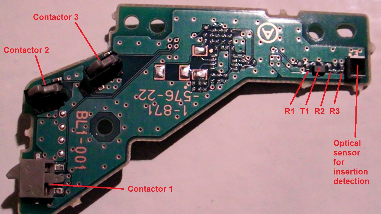
What we can see is that many components are not mounted.
The board functions are :
- Motor connection
- Contactors
- Insertion sensor
And now here is a fast schematics :

I've measured that 9 pin is GND.
I've also measured that 8 pin is Power supply and it is directly taken on pin 1 from the 60 pins PS3 connector.
I finally decided to draw the schematics with Word as they are easily and quickly done and they can be used by anyone. The schematics tools I wanted to used is way too heavy to handle for the time I can spend on it, and finding the components symbols I need is a real pain in the ass as I would have to create most of them !
So the word solution seems fine !
Well, that's all folks for today.
Monday, May 10, 2010
CPU pinout definition
For the CPU CXD5065GB-1 as I didn't find anything on a BGA 564 pins, I made an arbitrary pin identification for this component.
Here it is :

Here it is :

First look to the numerical sections !
Hi,
After the analog sections I've started to look to the numerical sections !
My first try is about the SPANSION Flash memory.
Here is some PCB analysis :

This is a closeup of the Flash's BGA package soldering.
The reference is AL008D0043-01, that's the marking on the package.
Of course this reference is under NDA so no datasheet is available for us !
Anyway, this component seems to be similar with the S29AL008D flash familly, where datasheet IS available.
What we can see first, is that an upper and a lower line of ball are spare because there are no trace leaving the balls. Must be to increase the component soldering, but anyway the E7 pin is connected to GND, so this can have a function.
Next, every pin on the datasheet can be found on the PCB as the pinout is always the same on these packages. And some of the not connected pins (NC) are used to increase the number of bits in the address bus to increase the memory's size.
Here I can identify 19 address lines plus 2 lines taken from the not connected ones.
Which would give us a 21 lines address bus.
Vcc and Vss pins have been confirmed on the board with my multimeter.
Another interesting thing to see is that every pin seems to be accessible using a via hole or by scratching the PCB traces to solder something on it to get a probe (using top and bottom, I can do some more measurements if you need it).
It is a pretty thougth thing to do, but for the ones who like to play, it seems possible to strobe the all memory's busses and have it going into a FPGA for example, and logging all bus accesses !
Ok that's done !
And feel free leaving a comment or answers to the open questions of the previous articles.
Sunday, May 2, 2010
Hi there !
I've found some time to examine (on the top side) another regulator section.
It is pretty close to the regulator 1 section as it is based on the TPS64203 Step down controller, a close friend of the TPS64201 !!
Here is a close up of the regulator components :

Here is the components identification for schematic :

I currently have a draft of this schematic, but the command circuit of the TPS64203's Enable input is getting deep into the board so it's harder to identify the schematic on this !
Here is the schematic of that section. I've made it with Word to have it quickly !
The Enable input is not complete, but it is linked with the rest of the board's design.

That's it for today !
Subscribe to:
Posts (Atom)
