Hi !
It is now time to present my new project : finding the thermal probes and analyzing their behavior toward fan control !
Confidential
As this is confidential materials, don't ask me the details I won't give them.
My goal is just to show what is possible, and I don't know yet the results !
Thermal Probe identifying on PS3 40Go
I spent a lot of time identifying components on the board, looking closely to get their marking and finding their datasheets !
And finally I GOT THEM, the thermal probes references and their datasheets !
They are three thermal probes components on the main-board.
- One for the RSX
- One for the CELL
- One for the main-board
The components for the RSX and the CELL have an external probe input, which must be connected to the CPU's and GPU's internal thermal probes. They also have both an internal thermal sensor. The third one is only internal sensor.
Reading the datasheets, is appears that there is a thermal alert control that must have been used by SONY to shut down the system. Maybe this is what is used when the XMB says that the system overheats and shuts it down.
Thermal system architecture
These all three components are SMB/I2C controlled, but they are slaves, so there must be a master in the system !
Starting from these components I used my multimeter to probe the main board and I finally found that they were related to the chipset of the main board. So it makes sense, as it is the same as in PC motherboards. The chipset configures thermal probes components, reads them with its firmware laws, and then with these information it controls the fan speed.
I guess it is all the same for the PS3 !
Let spy this !
I've started to probe a 40Go PS3 :

As I said, communication is a 3 wires I2C bus which has clock, bidirectionnal data and ground signals.
I've probed them on one of the thermal probes component, and now I have to design a I2C spy tool !

And as you can see on the front left of the test board there is a VGA connector which is directly accessed.
So now I have to design the test !
Complete system
Now I have the entire system :

Ok, first test design done, embedded logic analyzer is in place to watch I2C signals.
So I defined a trigger condition on a I2C START event to see I2C frames.
I armed the trigger and I powered up the PS3 at the back. Led is fixed red, PS3 in stand by, and there are I2C frames ! I Guess it is a security check to see if the PS3 can start in normal temperature conditions.
The frame is the following :
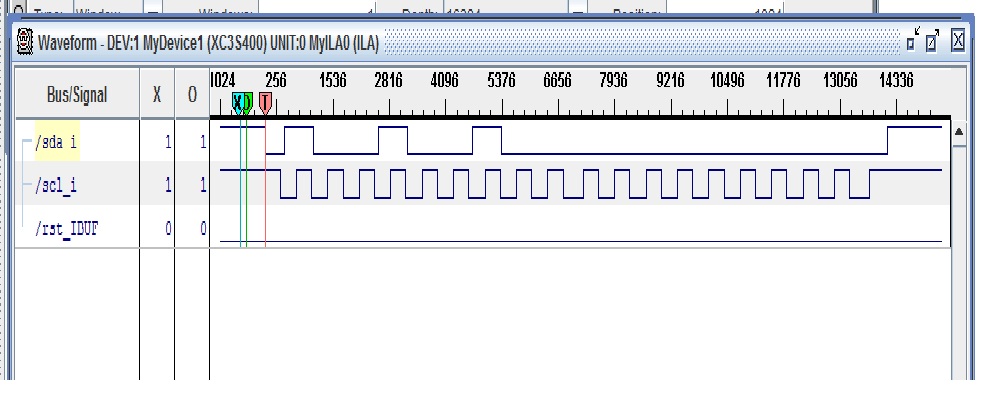
Now I have to analyze it using the components datasheets.
But the most important thing is that now I can spy what is happening on the I2C bus.
I have to make a test design that handles more advanced functions, like providing I2C address to identify the component addressed, extracting data types and values to define if it is components configuration, status or temperature measurements.
Steps done
- Made a state machine that extracts address field and data fields
- Created a microntroller architecture with UART and custom peripheral for i2c spy
- Basic software written, fixed bugs in test design. Still have problems to get data with processor !
- Fixed bugs, now data are printed in hyperterminal, Identified fields address, data, read/write. Almost done, but I have some processor resets and I2C extractions stalls, got to fix these. I will analyze datasheets to make extracted data interpretation.
- Fixed bugs, analyzed datasheets
GOT IT WORKING !!!
All right, I've got it working !
I have in my hyperterminal all the I2C traces that correspond to all the requests the chipset makes to the thermal probes.
Event if theses components have many functions, SONY only uses the temperature measurements and the defauts alert thresholds of these components !
Here is a hyperterminal capture :

These traces are half translated information.
The first letter represents the thermal probe addressed :
(Translated from I2C address extracted)
- B : motherboard probe
- C : CELL probe
- R : RSX probe
The second letter represents the I2C access :
(Translated from I2C access indentified)
- R : read
- W : write
The d: values are the real data on the I2C bus. I did not translate them as they are either configuration data, status data or temperatures data. For now my processor is not fast enought to handle the C lines I would have to write to data analysis and translate. Moreover, with UART printing times, I will miss I2C frames.
Never the less, when I manually translate temperatures data with datasheets binary encoding laws, I get the right teperatures !
And next ?
For now I don't really now what I will do with all this. But I will work in making a small product that could provide internal temperatures measures if you want to shut down your PS3 before temperature limits are reached.
I can associate it with the FAN PWM measurment to see how the PS3 uses the temperature measurements to handle fan speed.
And finally, the tool could take over the fan command with our own commmands !
I might post a video on youtube to show the tests !
Reproduction not allowed without permission.


